
Every vortex flow meter datasheet says fifteen diameters upstream and five downstream, and almost every installation site does not have fifteen diameters. That gap between the datasheet and the pipe rack is where most vortex meter accuracy problems begin, and it is worth understanding what the number actually buys you.
The requirement is not arbitrary. A vortex flow meter infers velocity from the frequency of vortex shedding, and that frequency depends on the shape of the velocity profile arriving at the bluff body. A distorted profile changes the effective Strouhal number, and vortex flow meter straight run reads wrong in a way that looks like a calibration drift.
On this page
Why the requirement exists
A bluff body in a pipe sheds vortices alternately from each edge. The shedding frequency is proportional to velocity divided by body width, with a proportionality constant called the Strouhal number. For a well designed body that constant is stable over a wide Reynolds range, which is what makes the measurement possible.
Stability depends on the flow arriving symmetrically. If the profile is skewed, the two shear layers separate differently, the shedding becomes uneven, and the frequency no longer represents the average velocity. vortex flow meter straight run does not fail. It reads a number that is consistently a few percent off.
That is the dangerous part. vortex flow meter straight run that fails reads zero and gets attention. A vortex flow meter straight run problem produces a plausible reading that nobody questions until an energy audit or a custody transfer dispute.
Where 15D and 5D come from
Fifteen diameters upstream is the length at which a single 90 degree elbow’s swirl has decayed enough that the profile is acceptably symmetric again. Five diameters downstream is where the vortex street has re-formed after the body and the pressure recovery is complete.
Those numbers assume a clean single disturbance. Add a second elbow in a different plane and the swirl becomes a corkscrew that persists much further. Add a partly closed valve and the jet can persist for thirty diameters.
This is why the standard answer is a floor, not a guarantee. A vortex flow meter straight run of exactly fifteen diameters after two elbows in different planes is not enough, and vortex flow meter straight run will read several percent high.
What each upstream fitting costs
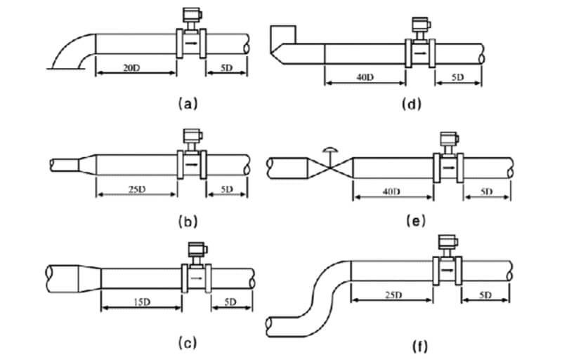
The table below is the practical version. These are the lengths that hold a one percent reading, not the theoretical minimum.
| Upstream fitting | Straight run needed |
|---|---|
| Long radius 90 degree elbow, single | 15 D |
| Short radius 90 degree elbow, single | 20 D |
| Two elbows in the same plane | 25 D |
| Two elbows in different planes | 40 D |
| Reducer, gradual | 15 D |
| Reducer, sudden | 20 D |
| Fully open gate valve | 15 D |
| Partly open control valve | 40 D or relocate |
| Pump discharge | 40 D or relocate |
| Thermowell | 5 D extra |
The two elbows in different planes case is the one that catches people. A pipe route that turns twice to avoid a beam looks innocent on a P and ID, and it is the worst upstream condition a vortex flow meter straight run can face.
Measuring the run you actually have
Count from the flange face of vortex flow meter straight run to the nearest disturbance, and count only straight pipe. A flexible coupling, an expansion joint, a reducer or a thermowell inside the run breaks it.
Measure along the centreline, not along the outside of the pipe. A run that looks long on a drawing is often shorter than expected once flanges and supports are accounted for.
If the number you get is below the table, you have three options and only three. Add pipe, add a conditioner, or change technology. Everything else is optimism.
Flow conditioners
A flow conditioner is a short insert that breaks up swirl and rebuilds a symmetric profile. A good one recovers most of the accuracy in five to seven diameters, which is why they are standard on skids.
They cost pressure, typically 0.1 to 0.3 bar depending on type and velocity. On a steam main that is a real operating cost, and it is worth comparing against the cost of a longer spool.
Not all conditioners are equal. A perforated plate conditioner works on swirl but not on a skewed profile. A tube bundle works on both but is longer. Ask for the conditioner’s own upstream requirement, because a conditioner that needs ten diameters in front of it has not solved anything.
Install the conditioner at the correct distance from vortex flow meter straight run. Too close and the profile has not re-formed. Too far and the swirl comes back. The manufacturer’s spacing is part of the specification, not a suggestion.
When you cannot get the length
Change technology. This is the honest answer more often than suppliers admit, and it saves projects.
A thermal gas mass flow meter needs one to two diameters and reads mass directly. On a gas line in a tight skid, it is usually the better instrument even though it costs more than a vortex meter.
A precession vortex flow meter needs three diameters because it generates its own swirl with guide blades. It is a gas instrument only, but on gas it solves exactly this problem.
An electromagnetic flowmeter needs five diameters on liquid and has no straight run sensitivity to swirl of the same kind, because it measures across the full bore.
If the fluid is steam and the run is short, a balanced orifice flow meter needs three to five diameters and handles the temperature. That combination is often the only practical answer on a retrofit steam line.
Downstream requirements
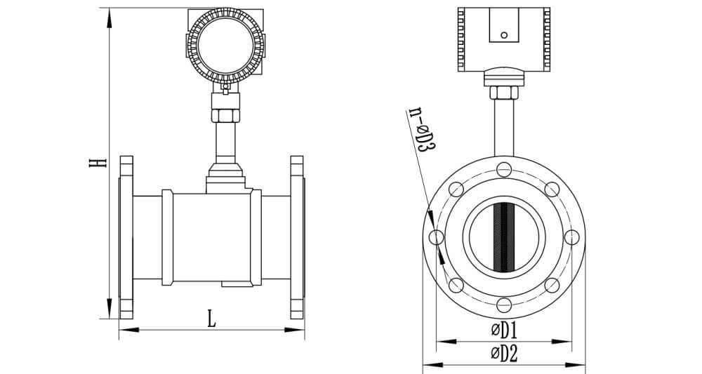
Five diameters downstream is the minimum, and it exists for a different reason. The vortex street takes a few diameters to break down, and a disturbance inside that zone can reflect pressure waves back into the shedding region.
In practice the downstream requirement is rarely the constraint, because there is usually pipe after vortex flow meter straight run. Where it does matter is vortex flow meter straight run installed directly onto a header or a vessel nozzle, with the fitting immediately after. Move it back.
Do not install a thermowell inside the downstream five diameters. A thermowell creates a wake that interacts with the vortex street and produces a periodic noise on the signal that looks like a flow oscillation.
Temperature and pressure ports
For compensated steam or gas measurement, the pressure tap goes downstream of vortex flow meter straight run at three to five diameters, and the temperature sensor goes further downstream at five to eight diameters.
That ordering matters. A thermowell upstream of vortex flow meter straight run destroys the profile. A pressure tap upstream disturbs it less but still disturbs it. Putting both downstream keeps the vortex flow meter straight run intact.
If vortex flow meter straight run is supplied with an integral pressure and temperature sensor, this whole section does not apply, which is one reason integrated units are popular on skids. The trade is that the sensors cannot be replaced without opening vortex flow meter straight run.
Vertical and inclined lines
Vertical upward flow is fine and often better than horizontal, because the profile is naturally axisymmetric and there is no gravity driven stratification on liquid.
Vertical downward flow is acceptable on gas and poor on liquid, because a falling liquid film on the wall distorts the profile and vortex flow meter straight run reads low. If the line must run downward, put vortex flow meter straight run in the horizontal section instead.
Inclined lines follow the horizontal rules. The requirement is about the last fifteen diameters before vortex flow meter straight run, and an incline inside that run counts as a bend.
A worked example on a real skid
A packaged boiler skid arrives with a DN80 steam line, a control valve, and a vortex flow meter squeezed between them. The drawing shows 300 mm of pipe between the valve outlet and vortex flow meter straight run flange. Is that enough?
300 mm on a DN80 line is 3.75 diameters. A partly open control valve needs forty diameters or relocation. vortex flow meter straight run will read, the reading will be plausible, and it will be wrong by a margin nobody can predict because it depends on how far the valve is open.
The options are the same three as always. Move vortex flow meter straight run downstream of the skid boundary, where there is straight pipe. Fit a conditioner, which buys maybe ten diameters of equivalent performance and costs pressure. Or change technology to something that does not care about the profile.
On steam, the practical answer is usually a balanced orifice meter, which needs three to five diameters and handles the temperature. On this skid, three diameters is exactly what the pipe run offers, and the pressure loss is lower than a vortex meter at the same duty.
What people actually do is install the vortex meter anyway and add a straightening vane welded into the spool. That sometimes works and it always depends on the valve position, which means the reading is right at design flow and wrong everywhere else.
How to verify a marginal installation
If you inherit a vortex flow meter with a straight run you are not sure about, there is a way to check without moving anything.
Compare vortex flow meter straight run against a clamp on ultrasonic meter at three flow rates. If the two agree across the range, the profile is acceptable at those points. If the vortex reads high at low flow and agrees at high flow, you have swirl. If it disagrees at all flows by a similar percentage, you have a calibration or a K-factor problem rather than a profile problem.
That comparison takes an afternoon and it is worth doing before a shutdown, because it tells you whether the pipework needs changing while the plant is still running.
Do the comparison at steady state. A vortex meter and an ultrasonic meter have different response times, so a ramping flow will show a difference that is not real.

Steam and gas are not the same
Most straight run tables are written for liquid, and gas is less forgiving. A gas stream carries swirl further because the density is low and the momentum that would dissipate it is smaller.
On steam, the density is high enough that a single elbow’s swirl decays in roughly the fifteen diameters the table quotes. On low pressure gas, the same swirl can persist for twenty five diameters, and a vortex meter installed at fifteen will read high by a couple of percent in a way that does not show up at the top of the range.
On compressed air at 7 bar the density is closer to steam and the fifteen diameter figure holds. On a 50 mbar gas main, no vortex meter should be installed at all, because the pressure loss alone rules it out.
The practical rule is to add five diameters for any gas below 1 bar gauge, and to treat the table as a floor rather than a target.
What the standard actually says
ISO 5167 defines the straight run requirements for differential pressure devices, not for vortex meters, but the disturbed profile lengths it specifies are the origin of most vortex tables. That matters because the numbers were derived for a different measurement principle and they are conservative in some cases and optimistic in others.
For a vortex meter, the sensitivity is to swirl rather than to a simple asymmetry. A symmetrical but distorted profile changes the reading less than a swirling one of the same magnitude, which is why two elbows in one plane need less straight run than two elbows in different planes.
Manufacturers publish their own requirements based on their own body geometry, and those numbers should take precedence over a generic table. A body with a longer bluff body and a deeper sensor pocket tolerates more disturbance than a compact one, which is one reason two meters of the same size from different suppliers can carry different straight run claims.
Ask for the requirement in writing with the quotation. A supplier who quotes fifteen diameters verbally and delivers vortex flow meter straight run that needs twenty five has given you a problem you cannot solve after the spool is welded.
What a wrong straight run actually costs
A vortex meter installed with half the required run typically reads two to four percent high. On a steam main moving 5 tonnes per hour, four percent is 200 kilograms per hour, and at a typical industrial steam cost that is a four figure annual number.
The error is invisible because it is consistent. vortex flow meter straight run is calibrated, it reads smoothly, the totaliser increments, and nobody has a reason to question it. The only things that expose it are a comparison audit, a mass balance that does not close, or an energy report that disagrees with the boiler’s own fuel figures.
That is the argument for spending money on pipe rather than on a better certificate. A one percent certificate on a badly installed meter is a four percent installation. A one and a half percent certificate on a properly installed meter is one and a half percent.
Common questions
Does a vortex flow meter straight run requirement change with pressure?
It changes with density. A high pressure gas behaves more like a liquid and the standard table applies. A low pressure gas needs more length, and a very low pressure main should not use a vortex meter at all because the pressure loss rules it out.
What is the minimum vortex flow meter straight run?
Fifteen diameters upstream and five downstream for a single elbow. Less than that and the reading depends on how distorted the profile happens to be, which is not a number anyone can defend.
Does a flow conditioner remove the requirement entirely?
No. A good conditioner reduces the upstream requirement to five to seven diameters. It does not eliminate it, and it adds pressure loss of its own.
Can I install a vortex flow meter after a control valve?
Only with forty diameters or a conditioner, and even then the throttling condition matters. A valve at 20 percent open produces a jet that no conditioner fully removes. Relocate if you can.
Why does my vortex flow meter read high?
Usually swirl. A single elbow too close rotates the profile, and vortex flow meter straight run reads high by two to four percent. Check the vortex flow meter straight run before you check the calibration.
Does the straight run change with pipe size?
The number of diameters is the same. The physical length is not, which is why a DN300 meter needs 4.5 metres upstream and a DN50 needs 0.75 metres.
Does insulation count as a disturbance?
No, but the thermowell under it does. A temperature sensor installed inside the upstream run breaks the straight pipe even though the pipe itself looks continuous.
Related reading
For vortex flow meter straight run itself, see the standard type vortex flow meter. For the wider selection decision, the flow meter selection guide covers the trade-offs between technologies. And if your meter is reading wrong rather than sitting in the wrong place, start with flow meter troubleshooting.
Reference for installation effects: ISO 5167 sets out the disturbed profile lengths that most straight run rules are derived from, and the reasoning applies to vortex meters as much as to differential pressure devices.
Working out velocity from your flow and bore? Use the flow rate and pipe velocity calculator before you settle on a line size.