
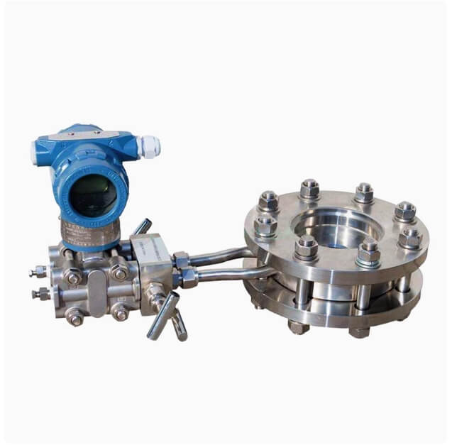

A balanced orifice flow meter solves the one problem a standard orifice plate cannot: it works in a short pipe run. A conventional plate needs ten to twenty diameters upstream to see a clean profile. A balanced plate, with its holes arranged across the bore, mixes the profile as the flow passes through it, so it needs three to five.
That single change is why balanced orifice flow meter gets specified on retrofit jobs, on offshore modules and on any skid where the pipe run was fixed before balanced orifice flow meter was chosen. You keep the orifice plate’s temperature and pressure range, its lack of moving parts, and its well understood uncertainty, and you give up the long straight run requirement.
On this page
- How the balanced orifice flow meter works
- Specifications
- Straight run and pressure loss
- Beta ratio and sizing
- Steam and high temperature service
- Erosion and dirty service
- Compared with standard orifice and vortex
- Installation
- Differential pressure transmitter selection
- Ordering checklist
- Common questions
How the balanced orifice flow meter works
The plate has several holes rather than one central bore. The holes are distributed so that the total open area equals the equivalent single bore, but the flow passes through them in a pattern that equalises velocity across the pipe section.
Downstream of the plate the jets merge into a much flatter profile than a single-bore plate produces. The result is a shorter wake, a faster pressure recovery, and a measurement that is far less sensitive to what happened upstream.
Why the profile matters
A standard orifice plate infers flow from the pressure difference across a known restriction. That inference assumes the flow arriving at the plate is symmetric. When it is not, the plate reads the local velocity rather than the average, and the error can reach several percent without any obvious symptom.
A balanced orifice flow meter is largely immune to that because the multi-hole pattern samples the whole section. It does not correct a swirl, but it averages it, and averaging is what you need.
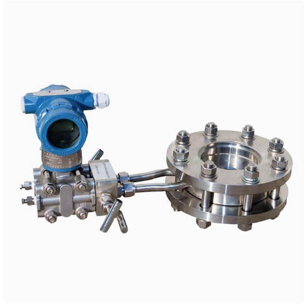
Specifications
| Parameter | Range |
|---|---|
| Nominal diameter | DN15 to DN1200 |
| Medium | Steam, gas, liquid, two-phase on request |
| Accuracy | plus or minus 0.5 percent of reading with a calibrated plate |
| Repeatability | 0.1 percent of reading |
| Turndown | 1:5 to 1:8, transmitter dependent |
| Beta ratio | 0.3 to 0.7 |
| Medium temperature | -40 C to +540 C |
| Nominal pressure | up to 40 MPa, flange class dependent |
| Plate material | SS316 standard, Hastelloy and Monel optional |
| Straight run | 3 to 5 DN upstream, 1 to 2 DN downstream |
| Permanent pressure loss | about one third of a standard orifice plate at the same beta |
| Output | 4-20 mA with HART, or 4-20 mA plus pulse |
The pressure rating is the headline. At 40 MPa and 540 C, no other technology in this price bracket comes close. A vortex meter stops at 400 C and 4 MPa. A thermal mass meter stops well below both. If the service is superheated steam at 100 bar, the orifice family is the only practical answer.
Straight run and pressure loss
Three to five diameters upstream against ten to twenty for a standard plate is the reason to buy balanced orifice flow meter. It is not a marginal improvement. On a DN200 line, fifteen diameters is three metres of straight pipe that has to be fabricated, supported and insulated.
The permanent pressure loss is roughly a third of a standard plate at the same beta ratio. On a steam main that runs all year, that difference is energy, and energy has a price. Run the annual cost before you compare purchase prices, because the cheaper plate is often the more expensive installation.
Neither number is free. The balanced plate costs more than a standard plate, and the multi-hole pattern is harder to machine. Whether that premium pays depends on how much straight run you do not have and how much pressure loss you cannot afford.


Beta ratio and sizing
Beta is the ratio of the equivalent bore to the pipe diameter. A low beta gives a larger differential for the same flow, which improves resolution but raises the permanent pressure loss. A high beta does the opposite.
The practical band is 0.3 to 0.7. Below 0.3 the loss becomes painful and the plate becomes sensitive to edge sharpness. Above 0.7 the differential gets small and the uncertainty grows faster than the loss falls.
Size for a differential of 100 to 250 mbar at normal flow if the transmitter allows it. That range sits comfortably inside a standard differential pressure transmitter’s accuracy band, and it leaves headroom for a flow increase without running out of span.
The transmitter sets the turndown
A balanced orifice flow meter’s turndown is limited by the differential pressure transmitter, not by the plate. A conventional transmitter with a 100:1 rangedown gives you a practical 1:5 to 1:8 flow turndown, because differential pressure falls with the square of flow.
If you need more, the answer is a smarter transmitter rather than a different plate. Some modern units hold accuracy down to a few percent of span, which extends the usable flow range considerably.
Steam and high temperature service
Superheated steam at 400 to 540 C is where the balanced orifice flow meter is at its best. The plate has no electronics in the hot zone, the transmitter sits on a cooling leg, and the whole assembly tolerates temperature cycling that would destroy a sensor based meter.
Condensing service needs care. Saturated steam will condense in the impulse lines unless they are traced and insulated, and a half-filled line gives a differential that has nothing to do with flow. Slope the lines back to the process, fit condensate pots, and trace them.
For wet steam, the plate reads high because the liquid phase has a different density and the two-phase relationship is not the single-phase one. If the dryness fraction varies, no differential device will give you an honest mass flow.
Erosion and dirty service
A single-bore plate erodes at the bore edge, and once the edge rounds the discharge coefficient changes permanently. A balanced plate distributes the flow across many holes, so each hole carries less energy and the edges hold their sharpness longer.
That is why balanced orifice flow meter is used on dirty gas and on services with trace sand. It is not immune, and on severe service you should specify a hardened plate and plan on replacement, but it lasts several times longer than a single bore.
Solid particles also tend to pass through the outer holes rather than concentrating at the centre, which reduces the local wear rate. The effect is real and it is measurable in service life.

Compared with standard orifice and vortex
| Balanced orifice | Standard orifice | Vortex | |
|---|---|---|---|
| Straight run | 3 to 5 DN | 10 to 20 DN | 15 DN |
| Permanent loss | Low | High | Low to moderate |
| Accuracy | 0.5 percent | 0.5 to 1.0 percent | 1.0 to 1.5 percent |
| Turndown | 1:5 to 1:8 | 1:3 to 1:5 | 1:10 to 1:15 |
| Temperature limit | 540 C | 540 C | 400 C |
| Pressure limit | 40 MPa | 40 MPa | 4 MPa |
| Dirty service | Good | Moderate | Good |
| Cost | Moderate | Low | Moderate to high |
Against a standard plate, the balanced version buys straight run and pressure loss with money. Against a vortex flow meter, it buys temperature and pressure range and gives up turndown. Against a gas turbine flow meter, it buys range and dirt tolerance and gives up accuracy at low flow.
Installation
- Three diameters upstream, two downstream. Count from the flange face.
- Fit the plate with the bevel facing downstream. This is the single most common installation error on any orifice plate.
- Centre the plate in the bore. An eccentric plate reads wrong and looks fine.
- Use the correct gasket and do not let it protrude into the bore. A protruding gasket changes the effective beta.
- Slope impulse lines and fit condensate pots on steam service.
- Mount the transmitter above the line for gas and below it for liquid, so any trapped phase drains the right way.
- Check the flange rating against the design pressure, not the operating pressure.
Differential pressure transmitter selection
The transmitter is half the measurement. A cheap transmitter on a good plate gives a cheap result, and the plate’s 0.5 percent claim assumes the differential is read to better than 0.1 percent of span.
Choose the span so that normal flow produces 60 to 80 percent of the differential range. That puts the working point where the transmitter is most accurate and leaves headroom for a process uprate.
For steam, specify a transmitter with a static pressure input so the density can be computed. For gas, add a temperature input. Without compensation, the plate measures volume at line conditions and the mass number is only as good as the assumptions behind it.
Ordering checklist
- Medium, and whether it is single phase
- Maximum, normal and minimum flow, with units and base conditions
- Line size, schedule, flange standard and pressure class
- Operating pressure and temperature, plus design values
- Beta ratio preference, or let us size it
- Plate and carrier material, and whether erosion is expected
- Transmitter: range, output, and whether compensation inputs are needed
- Straight run available upstream
A worked steam example
A DN150 steam main at 10 bar saturated, maximum 8 tonnes per hour, normal 5 tonnes per hour, minimum 1.2 tonnes per hour. Size the plate.
At 10 bar saturated the specific volume is about 0.194 m3/kg, so 8 t/h is 1,552 m3/h and 5 t/h is 970 m3/h. Through a DN150 bore the velocity at maximum is roughly 24 m/s, which is reasonable for steam.
Choose beta 0.55. The equivalent bore is 82.5 mm, and the differential at maximum works out near 200 mbar, which sits well inside a standard transmitter span. At the minimum of 1.2 t/h the differential falls to about 4.5 mbar, which is 2.2 percent of span and still readable on a good transmitter.
Check the permanent pressure loss. At beta 0.55 and 200 mbar differential, the permanent loss is roughly 30 to 40 mbar, against 100 to 120 mbar for a standard plate at the same beta. On a main running 6,000 hours a year, that difference is worth calculating in money before the purchase order goes out.
Now check the turndown. 8 t/h down to 1.2 t/h is 1:6.7, which is inside the 1:5 to 1:8 practical band but at the edge. If the minimum drops to 0.8 t/h the transmitter will be reading 1 percent of span and the uncertainty at that point is no longer 0.5 percent of reading. In that case, either accept a wider uncertainty at the bottom or split the range across two runs.
Impulse line practice
The plate is half the measurement and the impulse lines are the other half. Most of the bad readings we get asked about turn out to be impulse line problems rather than plate problems.
On steam, fit condensate pots at the same elevation on both sides and fill them before commissioning. Unequal condensate levels produce a standing differential that has nothing to do with flow, and it shows up as a zero offset that changes as the line heats and cools.
Slope horizontal impulse lines at least 1 in 12 back toward the process on gas, and toward the pots on steam. A horizontal line that is truly horizontal traps a slug of liquid and the reading becomes unstable.
Keep both lines the same length and the same bore. A short line on one side and a long line on the other responds to a flow change at a different rate, and the differential swings before it settles.
Blow the lines down before commissioning. Welding slag and mill scale in an impulse line will block a manifold port and the symptom looks exactly like a failed transmitter.
Installation faults that read as meter faults
A plate installed backwards reads low by a few percent and nobody notices until a comparison audit. The bevel goes downstream, always.
A gasket protruding into the bore changes the effective beta and reads high. Trim the gasket to the bore, or use a carrier with an integral gasket.
An eccentric plate reads high or low depending on where the holes ended up relative to the profile. Centre it and check the tap orientation before tightening.
A transmitter zeroed with the manifold open reads the static head rather than zero. Equalise, zero, then close. This is basic and it is still the most common commissioning error on a differential pressure installation.
Where the balanced orifice flow meter is the right answer
The balanced orifice flow meter is the right answer when three conditions hold at once. The service is hot or at high pressure, the pipe run is short, and the fluid is single phase. Remove any one of those and something else usually fits better.
Hot and high pressure is the first condition. A balanced orifice flow meter works to 540 C and 40 MPa, which puts it in a class of its own among meters that cost less than a Coriolis. Superheated steam, hot gas from a furnace, and high pressure process lines all fall inside that envelope.
Short pipe run is the second. A balanced orifice flow meter needs three to five diameters where a standard plate needs ten to twenty. On a skid, that difference is often the whole design margin, and it is the single reason most of these meters are sold.
Single phase is the third. A balanced orifice flow meter assumes one density, and it will produce a confident number on a two-phase flow that is simply wrong. If the fluid can flash or carry entrained gas, no differential pressure device is the right answer.
Where it is not the right answer
A balanced orifice flow meter is the wrong choice when the turndown requirement exceeds about 1:8. The differential falls with the square of flow, so a wide range means the transmitter is reading a few percent of span for most of the day, and the accuracy claim stops meaning anything.
It is the wrong choice when the pressure loss budget is generous and the budget for hardware is not. A standard orifice plate does the same job for less money if you have the straight run to feed it.
And it is the wrong choice on a line that runs at very low flow for most of the year. A thermal gas mass flow meter holds 1:100 turndown and reads mass directly, which on a gas line with a strong day-night swing is worth more than the temperature range.
What to send for a quote
A balanced orifice flow meter is sized, not picked from a list, so the enquiry needs process data rather than a part number. The eight items below are enough to size and price it.
- Fluid, and whether it is single phase
- Maximum, normal and minimum flow, with units and base conditions
- Operating pressure and temperature, plus design values
- Line size, schedule and flange standard
- Straight run available upstream and downstream
- Plate and carrier material, and whether erosion is expected
- Transmitter range and output, or whether we supply the transmitter
- Whether density compensation inputs are needed, and from which instruments
If the line size is not fixed, send the flow range and let us propose the size. A balanced orifice flow meter sized to fit an existing pipe is often a compromise, and the compromise shows up as a beta ratio outside the useful band.
Send a sketch if the pipe run is tight. A balanced orifice flow meter solves a short straight run problem, but it does not solve a zero straight run problem, and a sketch settles that in one look rather than three emails.
Common questions
How much straight run does a balanced orifice flow meter need?
Three to five diameters upstream and one to two downstream for most installations. Two elbows in different planes push that toward the top of the range. A balanced orifice flow meter installed with less than three diameters will still read, but the uncertainty is no longer the one on the certificate.
Is a balanced orifice flow meter more accurate than a standard orifice plate?
At the same beta and the same installation, yes, because the multi-hole pattern averages the profile. The bigger gain is that a balanced orifice flow meter holds its accuracy in a short run where a standard plate would not.
Can a balanced orifice flow meter handle two-phase flow?
Only with a dedicated two-phase solution. A standard balanced orifice flow meter will give a number, but that number assumes single phase and it will be wrong.
What turndown does a balanced orifice flow meter offer?
One to five or one to eight in practice, set by the differential pressure transmitter rather than the plate. If you need more than that, a balanced orifice flow meter is the wrong instrument and a vortex or turbine meter is the right one.
How often should a balanced orifice flow meter be inspected?
Every two to three years on clean service, annually on erosive service. Check the hole edges for rounding and the plate for bowing. A rounded edge changes the discharge coefficient of the balanced orifice flow meter and no amount of zeroing fixes it.
Can a balanced orifice flow meter be used on oxygen service?
Yes, with a compatible plate and carrier material and a cleaned assembly. Oxygen service rules out any grease or hydrocarbon contamination, so specify it at order rather than discovering it at commissioning.
Does a balanced orifice flow meter work on a vertical line?
Yes, with upward flow preferred. The plate itself is orientation independent, but the impulse lines and the transmitter mounting are not, so the installation drawing changes even though balanced orifice flow meter does not.
What is the smallest line size available?
DN15. Below that the hole pattern gets too fine to machine accurately and the uncertainty grows, so a small thermal mass meter or a variable arebalanced orifice flow meter is usually the better answer.
Related reading
If the straight run is short and the fluid is steam, the vortex flow meter is the other short-list option. If the fluid is clean gas and the pressure is moderate, a thermal gas mass flow meter reads mass directly. For the wider decision, start with the flow meter selection guide.
Reference for orifice metering standards: ISO 5167 defines the geometry and discharge coefficients that differential pressure meters are built against.