


A gas turbine flow meter is gas turbine flow meter most gas utilities and plant engineers reach for when they need custody-transfer accuracy on a clean, dry gas. A multi-blade rotor sits in the flow stream. The gas spins it. A magnetic pickup outside the body counts the blades as they pass, and the totaliser turns that pulse train into standard cubic metres.
The version we build puts temperature and pressure sensors inside the same housing, so gas turbine flow meter converts working-condition volume to base conditions on board. That detail matters more than most datasheets admit. gas turbine flow meter reading 100 m3/h at 8 bar and 40 C is moving a very different mass of gas than one reading 100 m3/h at 2 bar, and a trade settlement built on the wrong number is a dispute waiting to happen.
On this page
- What a gas turbine flow meter measures
- How the gas turbine flow meter works
- Gas turbine flow meter specifications
- Accuracy: what moves the number
- Sizing a gas turbine flow meter
- Temperature and pressure compensation
- Installation rules that decide whether it works
- Gas turbine flow meter vs vortex and Roots
- Where it fits, and where it does not
- Failure modes and what causes them
- Ordering checklist
- Questions we get every week
What a gas turbine flow meter measures
It measures volumetric flow at line conditions, then infers mass or standard volume from the gas state. The rotor speed is proportional to velocity, not to mass. If the gas density changes and you ignore it, the number on the display is still honest about volume and wrong about everything else.
This is why the compensated model outsells the basic one in gas distribution. City gate stations, district metering points and industrial boiler houses all see pressure and temperature swing through the day. An uncompensated meter there will track the swing and hand you a total that nobody can reconcile at month end.
Three quantities come out of a compensated unit. Actual volume flow, in cubic metres per hour at line conditions. Standard volume flow, corrected to 101.325 kPa and 20 C. And the accumulated total in standard cubic metres, which is the number the invoice is built on.
How the gas turbine flow meter works
Gas enters through a flow straightener, passes the rotor, and leaves through a diffuser. The straightener removes swirl so the rotor sees an even velocity profile. The diffuser recovers pressure that would otherwise be lost, which is why a well-designed turbine meter holds pressure loss near 0.3 to 0.5 bar at full scale.
The rotor and the bearing
The rotor is the only moving part, and the bearing under it decides the service life of the whole instrument. We use a tungsten carbide journal bearing for dry natural gas and a lubricated ball bearing where the gas carries trace oil or where gas turbine flow meter will sit idle for long periods. The carbide bearing tolerates contamination better. The ball bearing tolerates low flow better.
Blade count sets the pulse resolution. A 24-blade rotor on a DN50 body gives roughly 24 pulses per revolution, so low flow still produces a usable frequency. Go too fine and the pickup starts missing blades at the top of the range. Go too coarse and you lose resolution at the bottom.

K-factor and why it drifts
The K-factor is the number of pulses per cubic metre. On paper it is a constant. In service it is a curve that bends at the low end because the rotor is fighting bearing friction and gas drag across the blade tips. Every meter leaves the factory with its own calibrated curve, printed on the certificate and stored in the totaliser.
K-factor drift is the quiet failure mode. Nothing breaks. gas turbine flow meter keeps counting. Over two or three years the bearing wears, the rotor sits a few microns lower, and the K-factor moves by half a percent. On gas turbine flow meter moving 5,000 m3/h that half percent is 25 m3/h of unaccounted gas, every hour, and it will not show up until someone asks for a recalibration.
Most operators recalibrate on a three to five year cycle. If the gas is wet, if the pipe carries rust, or if gas turbine flow meter runs above 80 percent of its maximum range for long stretches, shorten that to two years. A turbine flow meter working principle guide covers the rotor and pickup in more detail if you are specifying a new installation.
Gas turbine flow meter specifications
The table below is the standard range. Sizes outside it are available on request, and the pressure rating follows the flange class you order rather than a fixed limit.
| Parameter | Range |
|---|---|
| Nominal diameter | DN25 to DN300 (DN15 to DN400 on request) |
| Accuracy | plus or minus 1.0 percent of reading, plus or minus 1.5 percent below 10 percent of range |
| Repeatability | 0.05 to 0.2 percent of reading |
| Rangeability | 1:20 standard, 1:30 on selected sizes |
| Nominal pressure | 1.6 MPa standard, 2.5 / 4.0 / 6.3 MPa optional |
| Medium temperature | -20 C to +80 C |
| Ambient temperature | -30 C to +60 C |
| Body and flange | Stainless steel or carbon steel with epoxy coating |
| Output | Pulse, 4-20 mA, RS485 Modbus, HART optional |
| Power supply | 24 VDC, or lithium battery for remote sites |
| Protection | IP65 standard, IP67 optional |
| Explosion protection | Ex ia IIC T4 Ga for the compensated head |
| Straight run required | 2 DN upstream, 1 DN downstream |
Two lines in that table deserve a second look. The accuracy statement is a percentage of reading, not of span. gas turbine flow meter quoted at 1.0 percent of span on a 1:20 range is really 20 percent of reading at the bottom of the range, and that is how good meters get sold badly. Ours is stated on reading so the comparison is honest.
The straight run figure of 2 DN upstream is short, and it is short because of the integral flow straightener. Without that straightener the same meter would ask for 10 DN to 20 DN. If you are replacing gas turbine flow meter in an existing skid with no room to move pipework, this is usually the deciding specification.

Accuracy: what moves the number
Published accuracy assumes a fully developed, swirl-free profile and a gas that matches the calibration gas. Real installations break both assumptions, and the error shows up as a bias rather than as noise, which makes it hard to spot in day-to-day readings.
Swirl is the biggest offender. A single elbow two diameters upstream can rotate the profile enough to shift the reading by one to two percent. The straightener absorbs most of it. An elbow in two planes, or a partly closed valve close to gas turbine flow meter, can defeat the straightener and you should add pipe length instead.
Pulsation from a reciprocating compressor is the second. The rotor has inertia, so it averages a pulsating flow rather than tracking it. Averaging is usually what you want, but it means gas turbine flow meter reads slightly high when the pulse amplitude is large, because the rotor coasts through the low half of the cycle.
Dirt is the third, and it is the one you can control. A 100 micron filter upstream of gas turbine flow meter removes the particles that score the bearing. Field data from gas distribution networks consistently shows meters on filtered lines holding their K-factor far longer than meters on unfiltered lines.
Sizing a gas turbine flow meter
Size on actual volumetric flow at operating conditions, then check that the result sits inside the range. Sizing on standard volume is the most common mistake we see, and it produces gas turbine flow meter that is two sizes too small and runs flat out from day one.
Rangeability
A 1:20 range on a DN80 body means a maximum of 400 m3/h and a minimum of 20 m3/h at line conditions. Below the minimum the rotor stalls and the output stops, which is worse than reading inaccurately because it looks like zero flow. If night-time demand drops below the minimum, either accept the blind spot or pick a wider-range meter.
For distribution metering with a strong day/night swing, check the minimum flow against the quietest hour of the quietest day, not against the annual average. That single check decides more sizing disputes than any other.
Pressure loss
Pressure loss rises with the square of flow. At full scale expect 0.3 to 0.5 bar on a clean meter. On a low-pressure network running at 30 mbar, half a bar of loss is impossible, so gas turbine flow meter has to be oversized until the loss fits the budget. That trade-off between turndown and pressure loss is the core of low-pressure gas sizing.
If the network cannot afford the loss, a rotary displacement meter or an insertion thermal mass meter is the better answer. Neither is a drop-in replacement, so decide before the pipework is fabricated.
Temperature and pressure compensation
The compensated head reads line pressure and line temperature, then solves for standard volume using the gas compressibility factor. For natural gas at moderate pressure the simple ideal-gas correction is within a fraction of a percent. Above 20 bar, or for gases with a high CO2 or hydrogen content, the correction needs a real compressibility factor and gas turbine flow meter has to be configured with the gas composition.
Configuration is where compensated meters go wrong in service. The base pressure, base temperature and gas composition live in a menu that someone sets once at commissioning and nobody revisits. Change the gas source, blend in biogas, or move gas turbine flow meter to a different pressure tier, and the total drifts without any alarm.
Write those three values on the commissioning sheet and keep it with gas turbine flow meter. It takes two minutes and it has settled more billing arguments than any calibration certificate.

Installation rules that decide whether it works
The mechanical rules are simple and they are the ones people skip when the pipework is already welded.
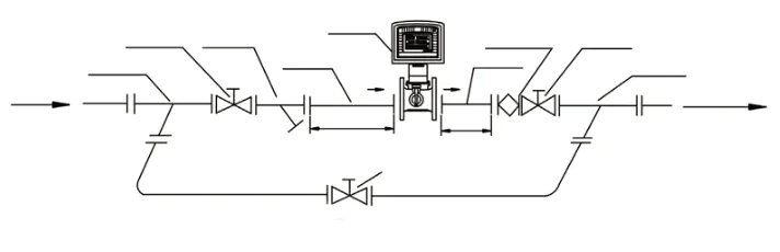
- Keep 2 DN of straight pipe upstream and 1 DN downstream. Measure from the flange face, not from the weld.
- Fit a filter at least 2 DN upstream. 100 micron is the usual choice for natural gas.
- Blow the line through before gas turbine flow meter goes in. Welding slag destroys a bearing in a week.
- Install horizontally with the totaliser readable. Vertical installation needs to be specified at order, because the rotor is trimmed for the flow direction.
- Match the arrow on the body to the flow direction. This sounds trivial and it is the most common commissioning error we see.
- Ground the body independently. Never share a ground with a high-voltage system.
- Add a bypass if the process cannot stop for maintenance. gas turbine flow meter you cannot service without shutting the plant is gas turbine flow meter that never gets serviced.
- Fit a steel expansion joint downstream where thermal growth is significant. It also makes the meter removable without cutting pipe.
Outdoor installations need a rain cover. Not for the electronics, which are sealed, but for the display window. Condensation on the inside of that window is the reason half the field photos we receive show an unreadable total.
Gas turbine flow meter vs vortex and Roots
All three measure gas volume. They differ in what they cost, what they tolerate, and where they stop working.
| Gas turbine | Vortex | Roots (rotary) | |
|---|---|---|---|
| Accuracy | plus or minus 1.0 percent of reading | plus or minus 1.0 to 1.5 percent of reading | plus or minus 1.0 percent of reading |
| Rangeability | 1:20 | 1:10 to 1:15 | 1:20 to 1:160 |
| Pressure loss | Low to moderate | Moderate, rises with the square of flow | Low |
| Minimum flow | Low, rotor stalls below range | Higher, needs a Reynolds number floor | Very low |
| Straight run | 2 DN up, 1 DN down | 15 DN up, 5 DN down | Minimal |
| Dirt tolerance | Poor, needs filtration | Good, no moving parts | Moderate |
| Moving parts | Rotor and bearing | None | Two rotors |
| Best for | Custody transfer on clean gas | Steam and dirty gas | Low pressure distribution |
The vortex meter wins wherever the gas is dirty or hot, simply because it has nothing to wear. It loses on turndown and it needs a long straight run that most skids do not have. The flange type vortex flow meter page covers that trade-off in detail.
The rotary meter wins on low pressure networks because it moves a fixed volume per revolution and does not care about the Reynolds number. It loses on capital cost at larger sizes and it dislikes dirty gas even more than a turbine does. See the gas Roots flow meter range for the size break points.
Where it fits, and where it does not
It fits custody transfer on dry natural gas, LPG vapour, compressed air and inert process gas. It fits any point where the gas is clean, the flow is steady enough for a rotor, and the budget cannot stretch to ultrasonic.
It does not fit wet gas, saturated steam, or any line where the gas can carry liquid droplets. A single slug of condensate will stop the rotor and, if it reaches the bearing, end its life. It does not fit dirty gas without filtration. And it does not fit a line that runs below 10 percent of range for most of the year, where a wider-range meter or a smaller body is the correct answer.
If you are still comparing technologies, our flow meter selection guide walks through the decision in the order an engineer actually makes it: fluid, then range, then accuracy, then pipework.
Failure modes and what causes them
Rotor stall at low flow shows up as a flat line at night. Check the minimum flow against the actual night-time demand before you blame the meter.
Reading low across the whole range usually means a worn bearing or a damaged rotor blade. Pull the meter, inspect the blade tips, and compare the K-factor against the certificate. A blade with a chipped leading edge will read low and it will do it consistently, which is why it gets mistaken for a calibration problem.
Reading high at high flow points at pulsation or at a partially blocked downstream strainer. Erratic readings with a periodic pattern point at a compressor cycle, not at the meter.
Zero output with gas flowing is almost always the pickup gap or the cable. Check the gap first. It is a two-minute check and it accounts for a surprising share of service calls.
Ordering checklist
Send these eight items with an enquiry and the quotation will be right the first time.
- Gas type and composition, including CO2 and H2S if present
- Nominal diameter and flange standard (ANSI, DIN or JIS) plus pressure class
- Maximum, normal and minimum flow, and whether those are at line or base conditions
- Operating pressure and temperature range
- Required accuracy and whether the point is custody transfer
- Output and protocol: pulse, 4-20 mA, RS485 or HART
- Power: 24 VDC or battery, and the expected battery life
- Hazardous area classification, if any
If you only have three of those, send the three. We would rather ask two questions than ship gas turbine flow meter sized on an assumption.
Questions we get every week
How often should a gas turbine flow meter be calibrated?
Every three to five years on clean dry gas. Every two years on wet gas, on lines with rust, or where the meter runs above 80 percent of range for long periods. Custody transfer points often follow a local metrology rule that overrides both numbers.
Can it measure in both directions?
The standard rotor is unidirectional. Bidirectional versions exist for storage applications, but they cost more and the accuracy statement is usually wider. If reverse flow is normal rather than an upset condition, specify it at order.
What is the minimum flow before the rotor stalls?
It depends on the body size and the gas density, which is why the range is quoted in actual cubic metres at operating conditions rather than in normal cubic metres. For a DN50 body on natural gas at 4 bar, the practical floor is around 3 to 5 m3/h. Ask for the curve for your size and pressure.
Does it work on compressed air?
Yes, and it is a common application. Compressed air is clean and dry after the dryer, which is exactly what the rotor wants. Size on actual flow at line pressure, and fit the filter anyway.
Why is my total different from the utility’s total?
Nine times out of ten the two meters are using different base conditions. Check base pressure and base temperature on both, then check the gas composition used for the compressibility correction. A difference of one or two percent is usually a configuration difference, not a hardware fault.
Related reading
For the rotor, pickup and K-factor in more detail, read how a turbine flow meter works. For liquid service on the same principle, see the flange type liquid turbine flow meter. And if you are still deciding between technologies, the selection guide is the shortest path from process data to a model number.
Reference for installation and metrology practice: NIST Handbook 44 covers the legal metrology requirements that most gas custody transfer rules are built on.