
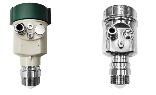
The reading was 62%. The tank was actually at 41%.
Nothing had failed. The 80 GHz radar level gauge was working exactly as designed, bouncing a signal off the first thing it could reflect from — which, after four months of service, was a 40 mm layer of foam sitting on top of the capture agent. The dosing controller had been adding make-up chemical against a foam line for most of a quarter.
Heavy metal capture agents — the DTC-type chelating agents used to precipitate copper, nickel, lead and cadmium out of plating and PCB wastewater — are one of the more awkward fluids to put a level instrument on. Understanding why explains most of the selection decisions that follow.
What is actually in the tank
Most liquid capture agents in commercial use are alkaline solutions of dithiocarbamate or xanthate derivatives, supplied at 10% to 40% active content. The numbers that matter for instrumentation:
| Property | Typical range | Why the instrument cares |
|---|---|---|
| pH | 9 to 12 | Attacks aluminium, galvanised parts, and many elastomers |
| Density | 1.05–1.25 g/cm³ | Defeats hydrostatic level if the batch varies |
| Viscosity | 20–500 mPa·s | Coats anything it drains past |
| Dielectric constant | High (aqueous, ε ≈ 60–80) | Good news for radar — strong reflection |
| Foaming tendency | Moderate to severe when agitated or dosed | The single biggest source of level error |
| Crystallisation | Below roughly 5–10°C | Winter storage, outdoor tanks, northern China |
| Suspended solids | 0–2% in some grades | Settles, and builds up on the tank floor |
Two of those rows are what make this application interesting. The high dielectric constant is a gift — radar reflects strongly off this liquid, so signal strength is never the problem. The foaming tendency is the curse, because a strong reflection off foam is still a strong reflection, just off the wrong surface.
Why the obvious instruments fail here
Float and mechanical gauges. The float gets coated, becomes heavier than its calibration assumes, and then sits low or sticks entirely. On a 500 mPa·s fluid with crystallisation risk, a mechanical float is a maintenance item, not a measurement.
Capacitive probes. Coating on the probe changes the dielectric between the electrodes, which is precisely what the instrument measures. The reading drifts steadily and silently as the film builds. A capture agent tank will coat a capacitive probe within weeks.
Hydrostatic pressure. Works only if density is constant. Capture agents vary batch to batch and dilute with condensate. A 5% density error is a 5% level error, and the diaphragm is also exposed to a scaling medium.
Ultrasonic. Sound speed changes with vapour concentration and temperature; foam absorbs the pulse outright; condensation on the transducer face blocks it. This is the worst of the common technologies for a warm alkaline tank in a humid plant room.
Radar, non-contact. Nothing in the medium, nothing to coat on the wetted side, and the reflection is strong. This is why radar became the default for chemical storage in the last decade.
Why 80 GHz rather than 26 GHz
Frequency determines beam angle, and beam angle determines how much of the tank you are looking at instead of the liquid.
| 26 GHz | 80 GHz | |
|---|---|---|
| Beam angle (DN40 lens) | 10°–12° | 3°–4° |
| Spot size at 5 m | ~0.9 m diameter | ~0.3 m diameter |
| Blocking distance | 0.3–0.5 m | 0.05–0.1 m |
| Resolution | ±5 mm typical | ±1 mm typical |
| Agitator and wall echoes | Frequent problem | Largely avoided |
A capture agent tank is usually small — 1 to 5 m tall, often under 2 m diameter — and often has a mixer, a dosing inlet, a heating coil or a recirculation line inside it. With a 10° beam at close range, the radar sees the agitator blades, the inlet stream and the opposite wall, and then has to sort them out in software. With a 3° beam, it looks down a narrow column of liquid and never sees them.
The shorter blocking distance matters just as much on a small tank. If the instrument cannot measure the top 0.4 m, you either lose 15% of usable volume on a 2.5 m tank or you mount it higher and lose accuracy at the bottom.
Keeping the accuracy: six things that decide it
1. Mounting position
Vertical, on the tank centreline if there is no agitator. Offset by at least 200 mm from the wall if the tank is small. Never over the inlet stream, never within the agitator sweep, and never where the beam can hit a heating coil or a ladder bracket.
On a tank with a top-mounted mixer, mount the gauge between the shaft and the wall, in a position where the beam cone at the lowest expected level still misses the blades.
2. Deal with foam deliberately
This is the accuracy question, not a footnote. Three options, in order of effectiveness:
- Break the foam. A stilling well or a bypass chamber gives the radar a quiet, foam-free surface to look at. If the tank already has a level bridle, put the radar on it.
- Measure through it. Thin, transient foam (under about 20 mm) is partly transparent at 80 GHz. Thick stable foam is not — the radar will report the foam surface, and on a dosing tank that is a systematic overstatement of inventory.
- Change technology. Guided wave radar travels along a probe and reads the liquid level beneath the foam in most cases, at the cost of a wetted probe that will need cleaning on a viscous medium.
Whichever you choose, log the reading against a manual dip for the first month. Foam behaviour is specific to the product, the agitator speed and the dosing rate, and no datasheet predicts it.
3. Condensation on the lens
A warm alkaline tank in an unheated plant room condenses water on a cold lens. A droplet sitting in front of the antenna is a false echo a few centimetres away, and the gauge will happily report it.
Fixes that work: a slightly protruding PTFE lens rather than a recessed one; a sunshade or insulation on the flange; a purge connection with a trickle of dry air; and, where the plant has instrument air anyway, a continuous low purge is the most reliable answer.
4. Scaling and product build-up
Capture agents leave a film. On the antenna that film attenuates the signal gradually — you do not get an alarm, you get a slowly falling signal strength and eventually a lost echo during a fill.
Specify a gauge that reports echo amplitude or signal-to-noise as a diagnostic value, and trend it. A drop of 30% over three months is your cleaning interval, decided by data instead of by failure. A purge ring or a wash nozzle on the flange makes the cleaning a two-minute job rather than a confined-space entry.
5. False echo suppression, set up properly
Every radar has an empty-spectrum or false-echo mapping routine, and it is almost always done badly at commissioning — performed on a tank that is half full, or not repeated after the agitator is installed.
Do it on an empty tank, with the agitator running, and redo it after any mechanical change inside the tank. Then verify at three known levels: low, mid, high, against a dip tape.
6. Verification routine
Non-contact radar does not drift the way a pressure transmitter does, but the installation around it changes. A quarterly check against a manual dip, recorded, catches the three things that actually go wrong: a coated lens, a shifted mounting, and a foam regime that changed with a new product batch.
Selection by scenario
| Scenario | Tank | Recommended | Watch for |
|---|---|---|---|
| Small PE/PP storage tank, no agitator | 1–3 m, DN500–DN1200 | 80 GHz non-contact, DN40 lens, 0–5 m range | Mount off-centre; check blocking distance |
| Dosing / dilution tank with mixer | 1.5–4 m | 80 GHz with stilling well, or guided wave radar | Beam must clear the blade sweep at low level |
| Foaming duty | Any | Guided wave radar, or non-contact in a bypass chamber | Probe will need periodic cleaning |
| Outdoor tank, winter crystallisation | Any | 80 GHz with heated flange or trace | Crystals on the lens look like an echo |
| Underground / sump pit | 0.5–2 m deep | 80 GHz, PTFE lens, IP67 | Vapour and condensation; provide a riser |
| FRP or plastic tank | Any | 80 GHz non-contact | Non-metallic wall is irrelevant to radar |
| Solvent-based grade, hazardous area | Any | Ex ia or Ex d certified 80 GHz | Specify certification at order, not after |
| Large bulk storage, 10 m+ | DN2000+ | 80 GHz, DN80 lens or 26 GHz | Beam spread is less critical at height |
Installation checklist
- Flange vertical within 1°. A tilted instrument measures a tilted path.
- Nozzle length under 100 mm, or use an extension that keeps the lens flush with the tank roof.
- Blocking distance set to the actual nozzle length plus a margin, not the datasheet minimum.
- 4-20 mA scaled to the usable volume, not the full tank height — a 20% dead band mapped into the signal is 20% of resolution thrown away.
- HART or RS485 back to the dosing controller, and the level alarm independent of the control loop.
- Earthing boss on the tank, cable shield grounded at one end only.
- Commissioning record: empty spectrum, three verification points, signal amplitude baseline.
Questions we get asked
Can radar see through the foam on a capture agent tank? Sometimes, and never reliably enough to design around. Thin transient foam yes; the 30–50 mm stable layer that forms on an agitated dosing tank, no. Assume the radar reads the foam surface and design accordingly.
Is the high pH a problem for the instrument? Not for a non-contact radar — nothing wetted except the lens material. It is a serious problem for probes, floats and diaphragms, which is one more argument for non-contact.
What accuracy is realistic? ±2 to ±5 mm on a clean installation, which is better than the dosing control loop needs. The practical error on these tanks comes from foam and mounting, not from the instrument.
Do I need a stilling well? If the tank has a mixer, a foaming product, or a diameter under 1 m, yes — it removes three problems at once and costs less than the rework.
How often should the lens be cleaned? Let the signal amplitude tell you. On most capture agent tanks it settles at every three to six months, with a purge fitted.
For the product specification behind these recommendations — range, beam angle, output options and process connection — see the 80 GHz radar level gauge page. If the tank sits inside a wastewater plant rather than a chemical store, the surrounding metering picture is covered in flow meters for wastewater treatment plants, and the material-compatibility logic for the dosing lines in liner and electrode selection for corrosive chemicals.