

An 80 GHz radar level gauge solves the problem that older radar could not: a small tank with a lot of internal structure. The higher frequency gives a narrower beam, and a narrower beam means the signal misses the agitator, the heating coil and the tank wall instead of bouncing off them.
That is the whole argument for 80 GHz in one sentence. Where a 26 GHz radar level gauge needs a stilling well or a large empty tank to work reliably, an 80 GHz unit with a 4 degree beam can be mounted in a 2 inch nozzle on a 1 metre tank with a mixer running and still read the surface.
On this page
- How the radar level gauge works
- 80 GHz against 26 GHz
- Specifications
- Beam angle and nozzle size
- Dielectric constant and what it changes
- Foam, condensation and agitation
- Mounting and tank geometry
- Commissioning
- Compared with ultrasonic and guided wave
- Where a radar level gauge stops
- Ordering checklist
- Common questions
How the radar level gauge works
The instrument transmits a frequency-modulated continuous wave downward, and the reflection from the liquid surface returns with a frequency offset proportional to the distance travelled. The radar level gauge measures that offset, converts it to a distance, and subtracts the distance from the tank height to give the level.
Because the measurement is time of flight, the speed of light is the only constant involved. Density, viscosity, temperature and pressure do not enter the calculation, which is why a radar level gauge keeps its accuracy when the product changes.
What 80 GHz changes
Higher frequency means a shorter wavelength, and a shorter wavelength allows a smaller antenna for the same beam angle. An 80 GHz radar level gauge with a 40 mm lens produces a beam about 4 degrees wide. A 26 GHz unit needs an 80 mm horn to get 10 degrees.
Smaller antenna, narrower beam, and better resolution. The 80 GHz radar level gauge also resolves closer to the antenna, so it works down to a few centimetres from the flange where older radar had a 30 cm dead zone.
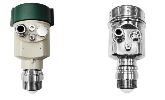
80 GHz against 26 GHz
| 80 GHz | 26 GHz | |
|---|---|---|
| Beam angle at 40 mm antenna | about 4 degrees | about 10 degrees |
| Minimum nozzle | 2 inch | 3 inch |
| Dead zone | 3 to 5 cm | 25 to 30 cm |
| Range | up to 120 m | up to 70 m |
| Accuracy | plus or minus 1 mm | plus or minus 3 mm |
| Foam penetration | Moderate | Better on thick foam |
| Price | Higher | Lower |
The 26 GHz radar level gauge still wins on one thing: thick foam. A lower frequency penetrates a foam layer better than a higher one, so a tank with a deep stable foam blanket is often better served by 26 GHz or by guided wave radar.
For everything else, the 80 GHz unit is easier to install because the nozzle can be small, and more reliable in a tank with internals because the beam misses them.
Specifications
| Parameter | Range |
|---|---|
| Frequency | 76 to 81 GHz |
| Measuring range | 0.05 to 120 m |
| Accuracy | plus or minus 1 mm |
| Beam angle | 4 degrees at 40 mm antenna |
| Process temperature | -40 C to +200 C |
| Process pressure | -1 to 40 bar |
| Dielectric constant | from 1.8 |
| Antenna | PTFE lens, or encapsulated horn for corrosive service |
| Process connection | Thread, flange, or clamp |
| Output | 4-20 mA with HART, RS485 Modbus |
| Power supply | 24 VDC, two wire loop powered, or 220 VAC |
| Protection | IP67, IP68 optional |
| Housing | Aluminium or stainless steel |
| Explosion protection | Ex ia IIC T6 Ga |
| Display | Local, with echo curve and diagnostics |
The 1 mm accuracy claim is only meaningful with a stable mounting and a clean surface. A radar level gauge bolted to a vibrating walkway will not hold a millimetre, and a tank with a boiling surface will not either.

Beam angle and nozzle size
The beam angle decides what the radar level gauge can see. A 4 degree beam from a 10 m mounting height spreads to about 0.7 m diameter at the surface. A 10 degree beam spreads to 1.75 m over the same distance.
That difference matters in a tank with a mixer. If the beam is wider than the clear area around the nozzle, it hits the agitator blades and the radar level gauge locks onto them instead of the liquid. A false echo from a stationary agitator is stable and plausible, which makes it the worst kind of fault.
Use the narrowest beam available, and mount away from the wall by at least the beam radius at the lowest level you need to measure. On a small tank that is a short distance. On a tall silo it can be a metre or more.
Nozzle and standpipe
A long narrow nozzle acts as a waveguide and can create a strong false echo at the nozzle outlet. Keep the nozzle short, or use the antenna extension that matches the nozzle length. The radar level gauge configuration includes a nozzle height parameter for exactly this reason, and leaving it at zero is a common commissioning error.
Dielectric constant and what it changes
Radar reflects from a change in dielectric constant, so the strength of the echo depends on the product. Water at 80 has a strong reflection. Most hydrocarbons at 2 have a weak one. Liquefied gas at 1.2 to 1.5 is close to the practical floor.
An 80 GHz radar level gauge with a lens antenna handles dielectric constants down to about 1.8 without a stilling well, which covers most solvents, oils and chemicals. Below that, the echo is weak and the instrument needs either a guided wave design or a stilling well to concentrate the reflection.
Where the dielectric is low and the tank has internal structure, the weak echo and the false echoes are the same magnitude and the instrument cannot tell them apart. That is the case where guided wave radar wins, and no amount of tuning fixes it.
Foam, condensation and agitation
Foam is the classic radar problem. A thin layer of surface foam reduces the echo. A thick stable foam absorbs the signal entirely and the radar level gauge reads the foam top or loses the echo, depending on the density.
Condensation on the antenna lens is the second. A droplet on a PTFE lens scatters the beam and produces a false echo close to the antenna. The purge or the self-cleaning lens option exists for this, and on a tank with a condensing vapour it is worth the money.
Agitation is the third. A moving surface scatters the reflection and the reading becomes noisy. Averaging in the electronics helps, but the real fix is to mount the radar level gauge where the surface is calmest, or to use a stilling well.
Mounting and tank geometry
- Mount vertically. A tilt of 2 degrees on a 10 m tank moves the beam a third of a metre off centre.
- Keep clear of the fill stream. The incoming liquid produces a false echo and a turbulent surface.
- Stay away from the wall by at least the beam radius at the lowest measured level.
- Enter the nozzle height and the tank height during commissioning. Both are used in the distance to level conversion.
- Use a flange or a threaded boss that keeps the lens flush with the tank roof. A recessed mounting creates a cavity echo.
- On an insulated tank, keep the electronics outside the insulation.
- Ground the housing, especially on a plastic or lined tank.
Commissioning
Every radar level gauge produces an echo curve, a plot of reflection amplitude against distance. Look at it before you accept the reading. The echo curve tells you immediately whether the instrument is locked onto the liquid or onto an agitator blade.
Run the empty tank calibration if the tank will ever be empty. The radar level gauge records the tank bottom echo and uses it as a reference, which improves accuracy at low levels.
Set the blocking distance honestly. A blocking distance set too small lets the radar level gauge report a level inside its own dead zone, which is a number it cannot actually measure.
Then map the false echoes. Most units allow you to store a suppression curve, and doing it once at commissioning saves a service call the first time the agitator runs.

Compared with ultrasonic and guided wave
| 80 GHz radar | Ultrasonic level | Guided wave radar | |
|---|---|---|---|
| Affected by vapour | Little | Strongly | Little |
| Affected by pressure | Little | No, but temperature drifts | Little |
| Foam | Moderate | Poor | Moderate |
| Low dielectric | Limited | Not applicable | Excellent |
| Internal structure | Narrow beam avoids it | Wide beam hits it | Probe ignores it |
| Contact with product | No | No | Yes |
| Cost | Moderate | Low | Moderate |
An ultrasonic level meter is cheaper and works well on water and wastewater in an open channel or a calm tank. Put it on a solvent tank with vapour and it fails, because sound speed depends on the vapour composition.
A guided wave radar level gauge puts a probe into the liquid and follows the pulse along it. It handles low dielectric products and internal structure better than free space radar, and it needs contact with the product, which rules it out for food and pharmaceutical service where hygiene matters.
Where a radar level gauge stops
Thick stable foam. The signal is absorbed and there is nothing to reflect from.
Very low dielectric products below 1.8. The echo is too weak without a stilling well.
Liquid with a boiling, rolling surface. The reflection scatters and the reading becomes noisy.
And tanks with a tall narrow nozzle and a wide beam. The nozzle echo dominates and the radar level gauge locks onto it. The fix is a smaller beam or a nozzle extension, not a firmware update.
Solids, silos and the dust problem
The same instrument measures the level of powder and pellets in a silo, and the rules change. A radar level gauge on a cement silo has to deal with a dust cloud that scatters the beam, a surface that forms an angle of repose rather than a flat plane, and a fill stream that drops from the top of the vessel.
Dust is the main problem. During filling, the airborne dust reflects the radar before it reaches the surface, and the radar level gauge reads the top of the dust cloud rather than the product. The reading is plausible and wrong, which is the worst combination.
Two options. Use a low frequency unit that penetrates dust better, or accept that the reading is only valid when the silo is settling. Most operators take the second and add a delay so the level is only logged a few minutes after filling stops.
The angle of repose is the second issue. A powder surface is not flat, and the radar level gauge measures the point where the beam hits, not the average. On a wide silo that point can be half a metre from the average level. For inventory that is usually acceptable. For a process that needs a true average, a multipoint arrangement or a 3D scanner is the right instrument.
Overfill protection and safety instrumented systems
A radar level gauge used for overfill protection is not the same product as a radar level gauge used for indication. The safety version needs a defined failure mode, a proof test interval, and a documented safety integrity level.
If the level signal is part of a safety instrumented system, specify the safety certified variant, not the standard one. The standard unit has a self-check routine and a diagnostic output, but that is not the same as a certified safety function with a declared probability of failure on demand.
Even on a non-safety installation, configure the overfill alarm independently of the level output. A single 4-20 mA signal that carries both the level and the alarm cannot be trusted when the loop fails, and a loop failure is exactly when you need the alarm.
Test the alarm on a schedule. A high level alarm that has never been triggered is an alarm nobody knows works, and the first time it matters is the first time it is tested.
Replacing an older gauge without cutting the tank
Most 80 GHz units are sold as replacements, and the reason is usually the nozzle. A tank built around a 26 GHz radar level gauge has a 3 inch or 4 inch nozzle, and a newer instrument with a smaller antenna drops straight in.
Check three dimensions before ordering: the nozzle diameter, the nozzle height and the flange standard. A radar level gauge with a lens antenna needs the lens to sit at or below the nozzle outlet, so a tall nozzle needs an extension. Getting that wrong produces a cavity echo that looks exactly like a false echo from tank structure.
If the old instrument was a guided wave unit, the probe comes out and the new radar level gauge goes into the same flange. That is the easiest upgrade in the plant, and it usually removes a probe that was coating or bending.
Keep the old instrument for a month. If the new reading disagrees with the old one, the old unit is the reference that tells you which one moved, and after a month nobody remembers what the original reading was.
Ordering checklist
- Tank height, diameter and the level range you need
- Product, dielectric constant, and whether foam is expected
- Process temperature and pressure
- Nozzle size and height, and whether a standpipe exists
- Internal structure: agitator, heating coil, baffles, fill stream
- Output and protocol
- Power supply and whether loop power is available
- Hazardous area classification, and whether the antenna must be encapsulated for corrosive vapour
Common questions
What range does an 80 GHz radar level gauge cover?
Up to 120 m on the long range version, and from about 5 cm from the flange at the near end. The near end is where 80 GHz beats 26 GHz, because the dead zone is a fraction of the older design.
Will a radar level gauge work through a plastic tank roof?
Yes, if the roof is non-conductive and the radar level gauge is mounted outside it. A plastic or fibreglass roof is transparent to radar, which is useful for tanks that cannot be opened.
Can a radar level gauge measure interface between two liquids?
Only with a dedicated interface version. A standard radar level gauge sees the strongest reflection, which is usually the upper surface.
Does foam affect a radar level gauge?
Yes. Thin foam is tolerable, thick stable foam absorbs the signal. If the tank foams heavily, a 26 GHz unit or a guided wave design is often more reliable.
What accuracy can I expect in a real tank?
Plus or minus 1 mm under reference conditions, and plus or minus 5 mm in a real tank with a moving surface and a moderate mounting. The gap is installation, not instrument.
Why does my radar level gauge show a fixed level that never changes?
It has locked onto a false echo, usually an agitator blade, a heating coil or a nozzle edge. Open the echo curve and look at where the peak is. Mapping the false echo fixes it.
Related reading
For flow rather than level, start with the flow meter selection guide. If the application is water and the tank is open, an ultrasonic flow meter may cover the flow side of the same project.
Reference for radar level practice: IEC 62541 and the vendor echo curve documentation are the two things worth reading before commissioning a tank with internal structure.