
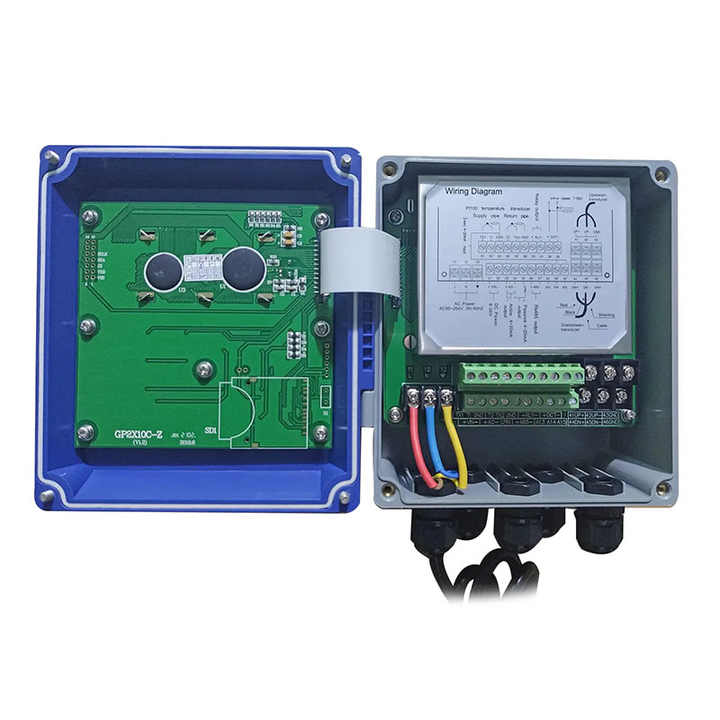

A clamp on ultrasonic flow meter measures from outside the pipe. Two transducers strap to the wall, one fires a pulse through the fluid and the other listens, and the difference in transit time up and downstream gives the velocity. Nothing touches the water, nothing is cut, and nothing has to be shut down to install it.
That is why these meters get bought by plants that cannot stop. A cooling water main that feeds a data centre, a district heating loop that runs all winter, a fire main that must stay live. In every one of those cases the alternative to a clamp on ultrasonic flow meter is a shutdown that costs more than clamp on ultrasonic flow meter by an order of magnitude.
On this page
- How the clamp on ultrasonic flow meter works
- Specifications
- Pipe and fluid requirements
- What decides the accuracy
- Installation: the part that goes wrong
- Clamp on versus inline
- Where it earns its keep
- BTU and energy metering
- Where a clamp on ultrasonic flow meter fails
- Using one for a survey
- Ordering checklist
- Common questions
How the clamp on ultrasonic flow meter works
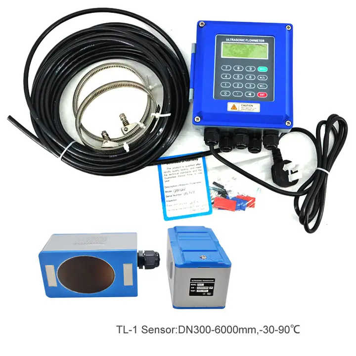
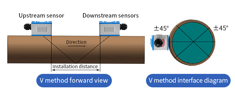
Two transducers are mounted on the outside of the pipe, offset from each other so the sound path crosses the fluid at an angle. Each transducer both sends and receives. The upstream transducer fires into the flow, the downstream one fires against it, and the difference in transit time is proportional to the average velocity along the path.
The measurement is a time difference of nanoseconds, so the electronics matter as much as the transducers. A modern clamp on ultrasonic flow meter resolves that difference reliably enough to hold one percent on a clean pipe, which is remarkable given that the sound has to cross the pipe wall, a coupling layer, and the fluid.
Why the pipe wall matters
The sound crosses the wall twice, and the wall’s thickness and material enter the calculation. Get the wall thickness wrong by a millimetre on a thin pipe and the error is small. Get the material wrong, steel instead of cast iron, and the error is several percent.
That is why every installation starts with a pipe measurement, not a menu selection. A clamp on ultrasonic flow meter configured for the wrong wall thickness will read consistently wrong, and it will look like clamp on ultrasonic flow meter fault when it is a setup fault.
Specifications
| Parameter | Range |
|---|---|
| Nominal diameter | DN32 to DN6000 |
| Pipe material | Steel, stainless, cast iron, copper, PVC, HDPE, cement lined |
| Accuracy | plus or minus 1.0 percent of reading, plus or minus 0.5 percent with a calibrated installation |
| Repeatability | 0.2 percent of reading |
| Velocity range | 0.03 to 12 m/s, bidirectional |
| Fluid temperature | -40 C to +160 C, higher with high temperature transducers |
| Fluid requirement | Single phase, and carries sound. Water, seawater, oil, most chemicals |
| Turbidity limit | up to 10,000 ppm suspended solids, above that use Doppler |
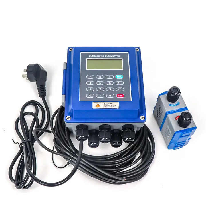
| Output | 4-20 mA, pulse, RS485 Modbus, HART optional |
| Power supply | 24 VDC, 220 VAC, or battery for portable units |
| Protection | IP65 for the converter, IP68 for transducers |
| Data logging | Built in, typically 60,000 readings or more |
The DN32 floor is real. Below that the sound path gets short, the time difference gets small, and the uncertainty grows faster than the specification admits. For small pipes, an inline electromagnetic or a small turbine meter is the better answer.
Pipe and fluid requirements
The pipe has to carry sound. Steel, stainless steel, cast iron, copper, PVC and HDPE all work. Concrete and heavily lined pipes do not, unless the liner is thin and bonded. Ductile iron with a cement lining is the classic problem case, and the answer is to mount the transducers on a section of unlined pipe or use an insertion type instead.
The fluid has to be single phase and reasonably homogeneous. Clean water is ideal. Seawater works. Oil works, though the sound speed is lower and the setup needs the right fluid properties. A fluid full of bubbles does not work, because the sound scatters and the signal is lost.
Slurries are a different case. Up to about 10,000 ppm of suspended solids, a clamp on ultrasonic flow meter still works on transit time. Above that, the signal attenuates and you need the Doppler variant, which measures the frequency shift from particles rather than the transit time.
Liner and coating problems
An internal liner that has delaminated from the pipe wall will reflect the sound and clamp on ultrasonic flow meter reads nothing or reads nonsense. A thick external paint or a bitumen coating has to be removed where the transducers sit. Both are visible in the field and both get missed.
What decides the accuracy
Five things, in order of impact. The pipe dimensions, the transducer spacing, the number of paths, the flow profile, and the fluid properties.
Pipe dimensions come first because everything else is scaled from them. Measure the outside diameter with a tape and the wall thickness with an ultrasonic thickness gauge. Do not use the nominal size. A DN200 steel pipe is not 200 mm inside, and a 2 mm error in wall thickness moves the reading by more than one percent.
Transducer spacing comes second. clamp on ultrasonic flow meter calculates a spacing from the pipe data and the fluid sound speed, and the transducers have to be mounted at that spacing to within a millimetre. A rail or a mounting frame makes that repeatable. Eyeballing it with a tape does not.
Path number comes third. A single path meter assumes an axisymmetric profile. Two paths across the diameter, or four paths, average out asymmetry and are the standard for custody transfer and for large pipes. On a DN1200 main, a single path clamp on ultrasonic flow meter can be two or three percent off in a short straight run.
Installation: the part that goes wrong
Most clamp on ultrasonic flow meter problems are installation problems, and they all look like instrument failures. Work through this list before blaming the electronics.
- Ten diameters upstream and five downstream. On a large pipe that is a long way, and a short run is the most common cause of a reading that drifts with flow.
- Mount on the side of a horizontal pipe, at three or four o’clock. Top mounting traps air, bottom mounting traps sediment.
- Remove paint, rust and scale where the transducers sit. The surface has to be smooth and bare.
- Use enough coupling compound. Too little gives a weak signal and an unstable reading.
- Clamp firmly and evenly. A transducer that moves by a fraction of a millimetre loses the signal.
- Enter the real wall thickness and material. This is the step people skip.
- Check the signal strength and the signal quality indicator before you trust the number.
The signal quality indicator is the most useful diagnostic on the meter. A strong signal with a poor quality reading means the setup is wrong. A weak signal means the coupling or the pipe is wrong. Learn what a good installation looks like on a known pipe, and you will spot a bad one in seconds.
Clamp on versus inline
| Clamp on | Inline | |
|---|---|---|
| Installation | No cutting, no shutdown | Pipe cut, shutdown required |
| Accuracy | 1.0 percent typical | 0.5 percent typical |
| Cost at DN300 | Low | High |
| Cost at DN50 | High relative to pipe | Moderate |
| Straight run | 10 DN up | 5 DN up |
| Maintenance | Transducers can be re-greased | Spool removal |
| Best for | Retrofit and large pipe | New build and small pipe |
The economics flip with size. At DN50 an inline meter costs less than a clamp on ultrasonic flow meter and is more accurate. At DN600 the inline meter is a fabrication project and the clamp on unit is a morning’s work.
For a new build, specify inline. For a retrofit, a survey, or a temporary measurement, a clamp on ultrasonic flow meter is almost always the right answer.
Where it earns its keep
Cooling water and condenser circuits, where the pipe cannot be opened. District heating and cooling loops, where the meter doubles as a BTU meter. Fire main testing, where a temporary clamp on ultrasonic flow meter verifies pump performance without disrupting the system.
Seawater systems on ships and coastal plants, where an inline meter would corrode. Raw water intake, where the pipe is large and the budget is not.
And leak detection on buried or inaccessible mains, where the meter is the only way to compare supply against demand without excavating.
BTU and energy metering
Add a pair of temperature sensors and the clamp on ultrasonic flow meter becomes an energy meter. Flow times the temperature difference times the specific heat gives thermal power, and the total gives energy in kWh or GJ.
The flow measurement is the accurate part. The temperature difference is the weak link, because a 5 C difference measured with two sensors each accurate to 0.5 C carries a ten percent uncertainty on the difference. Use matched sensor pairs and calibrate them together.
For billing, check the local rule. Many jurisdictions require a certified heat meter rather than a flow meter with two sensors, and a clamp on ultrasonic flow meter configured as a BTU meter may not satisfy that requirement even when it is more accurate.
Where a clamp on ultrasonic flow meter fails
Gas. Sound does not travel well in low pressure gas and the impedance mismatch at the pipe wall is severe. A clamp on ultrasonic flow meter on a gas line is possible at high pressure with special transducers, and it is not a general purpose solution.
Very small pipes. Below DN32 the time difference is too small to resolve reliably.
Lined or coated pipes. The liner reflects or attenuates the sound.
Heavy slurry. Above 10,000 ppm the transit time method loses the signal, and you need Doppler.
And pipes with a strong external vibration. The transducers move relative to the pipe and the signal drops out intermittently.
Using one for a survey
A portable clamp on ultrasonic flow meter is the standard tool for a plant-wide flow survey, and the method is straightforward. Pick the measurement points from a drawing first, then work through them in one pass so the readings are comparable.
Record the signal quality alongside every reading. A reading taken at a poor signal quality is not a data point, it is a guess, and it will distort the survey. Mark those points and come back with better pipe preparation.
Take the survey at a steady state. A cooling circuit that is ramping up or down gives numbers that cannot be compared with anything, and the report will be useless however carefully the meter was set up.
Mounting frames and repeatability
A clamp on ultrasonic flow meter is only as repeatable as its transducer mounting. Straps and tape work for a survey that lasts an afternoon. They do not work for a permanent installation, because the transducers creep, the coupling dries out and the spacing drifts.
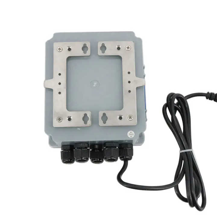
Use a mounting frame for anything permanent. A stainless rail with fixed transducer carriages holds the spacing to a fraction of a millimetre, and it can be re-greased without re-measuring. On a large pipe, the frame is a small fraction of the total cost and it decides whether the installation is still accurate in three years.
For high temperature service, the transducers sit on standoffs or on a wave guide so the piezo elements stay cool. A clamp on ultrasonic flow meter on a 140 C heating line with transducers bonded directly to the pipe will fail within months, and the failure looks like a gradual loss of signal rather than a clean break.
Mark the transducer positions on the pipe with a paint pen once the installation is proven. When someone removes them for maintenance, the mark is what gets the meter back to the same reading.
Diagnosing a weak signal
Every clamp on ultrasonic flow meter has a signal strength and a signal quality reading. Learn what a good installation looks like, then work down this list when the numbers fall.
- Coupling compound dried out or never applied properly. Re-grease and retest. This fixes most cases.
- Pipe surface not prepared. Paint, rust and scale scatter the sound.
- Transducer spacing wrong for the entered pipe data. Re-measure the pipe and recalculate.
- Wrong pipe material selected. Cast iron and steel have different sound speeds.
- Air in the line. A high point or a partly empty pipe loses the signal entirely.
- Liner delaminated from the wall. The sound reflects and the reading disappears.
- Transducer cable damaged or a connector corroded. Swap the cable and retest.
Work through the list in order. Most weak signal reports are solved by the first two items, and the rest are rare enough that they are worth checking only after the cheap fixes have failed.
Cost of ownership
A clamp on ultrasonic flow meter costs more than an inline mechanical meter at small sizes and much less at large sizes. The crossover is around DN100 on a new build, and around DN50 on a retrofit where the shutdown cost is counted.
Running costs are low. There are no moving parts, no bearing to replace and no spool to pull. The coupling compound needs refreshing every few years, and the transducers last a decade or more on a clean pipe.
The hidden cost is the setup time. A careful installation with measured pipe dimensions takes two to three hours. A rushed one takes forty minutes and reads two percent wrong for the next five years. Budget the time.
Ordering checklist
- Pipe outside diameter, wall thickness and material, measured rather than assumed
- Fluid, temperature, and whether it carries suspended solids
- Flow range and the direction, if reverse flow occurs
- Straight run available upstream and downstream
- Number of paths: one for indication, two or four for billing
- Output, protocol and whether a logger is needed
- Power available on site
- Whether the transducers need IP68 for a flooded pit
Common questions
Does a clamp on ultrasonic flow meter need the pipe emptied?
No. That is the main reason to use one. The transducers mount on the outside and the line stays in service.
How accurate is a clamp on ultrasonic flow meter in practice?
One percent of reading on a good installation with measured pipe dimensions and a clean profile. Half a percent is achievable with a calibrated two path unit, and two to three percent is what you get when the pipe data is guessed.
Will a clamp on ultrasonic flow meter work on plastic pipe?
Yes, and often better than on metal, because there is no scale and the sound coupling is good. PVC and HDPE both work well, and HDPE needs the wall thickness measured carefully because it varies.
What is the minimum pipe size?
DN32 for reliable transit time measurement. Below that the uncertainty grows quickly and an inline meter is the better choice.
Can it measure dirty water?
Up to about 10,000 ppm of suspended solids. Above that the signal attenuates and a Doppler meter is the right instrument.
Why does my clamp on ultrasonic flow meter read zero?
Usually the signal. Check the coupling compound, the pipe surface preparation, the transducer spacing and the entered wall thickness, in that order. The electronics rarely fail.
Related reading
If the pipe can be opened and the fluid is conductive, an electromagnetic flow meter gives better accuracy for similar money. If you are comparing the two technologies, read electromagnetic versus ultrasonic flow meters. For gas rather than liquid, a thermal gas mass flow meter reads mass directly.
Reference for ultrasonic metering practice: ISO 12242 covers transit time ultrasonic meters for closed conduits and sets out the installation conditions that accuracy claims depend on.