

Introduction
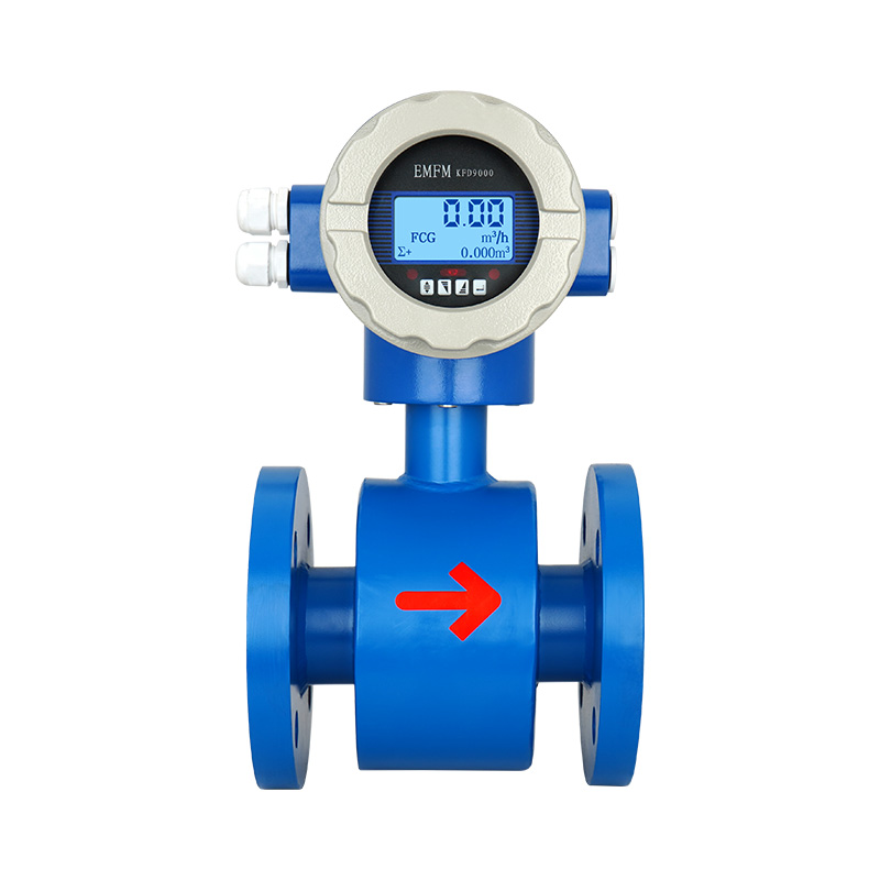
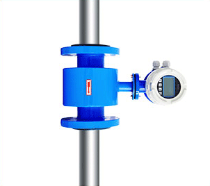
Flange electromagnetic flowmeter is a flowmeter that tests flow based on Faraday’s law of electromagnetic induction. Flange electromagnetic flowmeter has been used worldwide for more than half a century. The advantages of flange electromagnetic flowmeter are extremely small pressure loss and a large measurable flow range. The ratio of maximum flow to minimum flow is generally above 10:1. The applicable industrial pipe diameter range is wide, up to 3m. The output signal and the measured flow are linear, with high accuracy. It can measure the flow of acid, alkali salt solution, water, sewage, corrosive liquid, mud, ore pulp, pulp and other fluids with conductivity ≥5μs/cm.
Advantages
Advantages and Disadvantages of Flange Electromagnetic Flowmeter:
The main advantage of flange electromagnetic flowmeter is that it has no moving parts, no pressure loss, and extremely low maintenance cost.
The flange electromagnetic flowmeter has a wide range of calibers, from DN15 to DN3000mm, and can measure flow in both directions. The electromagnetic flowmeter has built-in self-diagnosis function, supports data logging/Bluetooth function and multiple output signals.
Compared with other liquid flowmeters, the limitation of flange electromagnetic flowmeter is that it can only be used for conductive liquids. For non-conductive or low-conductive liquids, such as petroleum products, organic solvents, it cannot be used. If there is a strong magnetic field in the surrounding environment, the flange electromagnetic flowmeter will be affected.
Application
Flange electromagnetic flowmeter installation requirements:
Flange electromagnetic flowmeters are widely used in process flow measurement and control of industrial and agricultural production enterprises such as iron and steel metallurgy, water supply and drainage, Water conservancy and irrigation, water treatment, sewage treatment stations (environmental sewage control, chemical sewage, electroplating sewage), paper mills (pulp), mud, petrochemicals, medicine, food, etc.
In the iron and steel metallurgical industry, it is often used for cooling water flow control of continuous casting steel, continuous rolling steel, and steelmaking electric furnaces;
In the field of public utility water supply and drainage, it is often used for finished water and raw water transportation and metering in water plants, and lightning protection functions can be customized, which can be used in areas prone to lightning strikes;
In the pulping process of the papermaking industry, electromagnetic flowmeters involve the flow measurement of pulping, water, acid, and alkali;
In the coal industry, it is used for coal washing metering and pipeline pressure water transportation of coal sludge;
In the food and beverage industry, it is used for filling metering of beer and beverages; in the chemical and petrochemical industries, it is used to measure the flow of corrosive liquids such as acids and alkalis.

| Size | DN15-DN3000mm |
| Nominal Pressure | 0.6-1.6Mpa(2.5Mpa/4.0Mpa/6.4Mpa…Max 42Mpa) |
| Accuracy | +/-0.5%(Standard) +/-0.3% or +/-0.2%(Optional) |
| Liner | PTFE, Neoprene, Hard Rubber, EPDM, FEP, Polyurethane, PFA |
| Electrode | SUS316L, Hastelloy B, Hastelloy C Titanium, Tantalum, Platinium-iridium |
| Structure Type | Integral type, remote type, submersible type, ex-proof type |
| Medium Temperature | -20~+60 degC(Integral type) |
| Remote type(Neoprene,Hard Rubber,Polyurethane,EPDM) -10~+80degC Remote type(PTFE/PFA/FEP) -10~+160degC |
|
| Ambient Temperature | -20~+60deg C |
| Ambient Humidity | 5-100%RH(relative humidity) |
| Measuring Range | Max 15m/s |
| Conductivity | >5us/cm |
| Protection Class | IP65(Standard); IP68(Optional for remote type) |
| Process Connection | Flange (Standard), Wafer, Thread, Tri-clamp etc (Optional) |
| Output Signal | 4-20mA/Pulse |
| Communication | RS485(Standard), HART(Optional),GPRS/GSM (Optional) |
| Power Supply | AC220V (can be used for AC85-250V) DC24V (can be used for DC20-36V) DC12V (optional), Battery Powered 3.6V (optional) |
| Power Consumption | <20W |
| Alarm | Upper Limit Alarm / Lower Limit Alarm |
| Self-diagnosis | Empty Pipe Alarm, Exciting Alarm |
| Explosion Proof | ATEX |
| Electrode Material | Applications & Properties |
| SUS316L | Applicable to industrial/municipal water, wastewater and low corrosive mediums. Widely used in petroleum, chemical industries. |
| Hastelloy B | Strong resistance to hydrochloric acids below the boiling point. Resist against oxidable acids, alkali and non-oxidable salts. For instance, vitriol, phosphate, hydrofluoric acids, and organic acids. |
| Hastelloy C | Exceptional resistance to strong solutions of oxidizing salts and acids. For example, Fe+++, Cu++, Nitric acids, mixed acids |
| Titanium | Titanium can withstand corrosive mediums such as seawater, chloride salt solutions, hypochlorite salts, oxidable acids(including fuming nitric acids), organic acids, and alkali. Not resistant to high purity reducing acids such as sulphuric acids, hydrochloric acids. |
| Tantalum | Highly resistant to corrosive mediums. Applicable to all chemical mediums except Hydrofluoric Acids, Oleum and Alkali. |
| Platinum-iridium | Applicable to all chemical mediums except for Ammonium salts and Fortis |
Table 3: Flange Magnetic Flow Meter Selection Guide
| QTLD | X | X | X | X | X | X | X | X | X | X | X | |
| Caliber size | DN3-DN3000 (1/8″-120″) | |||||||||||
Structure |
Compact | 1 | ||||||||||
| Remote | 2 | |||||||||||
| Compact with explosion proof | 3 | |||||||||||
| Remote with explosion proof | 4 | |||||||||||
Accuracy |
±0.5% | 1 | ||||||||||
| ±0.2% | 2 | |||||||||||
| Others | 3 | |||||||||||
Lining Material |
PTFE | 1 | ||||||||||
| FEP | 2 | |||||||||||
| PFA | 3 | |||||||||||
| Neoprene | 4 | |||||||||||
| Polyurethane | 5 | |||||||||||
| Hard Rubber | 6 | |||||||||||
| Ceramic | 7 | |||||||||||
| Others | 8 | |||||||||||
Electrode Material |
SS316L | 1 | ||||||||||
| Hastelloy B | 2 | |||||||||||
| Hastelloy C | 3 | |||||||||||
| Titanium | 4 | |||||||||||
| Tantalum | 5 | |||||||||||
| Platinum-iridium | 6 | |||||||||||
| Stainless steel covered with tungsten carbide | 7 | |||||||||||
| Others | 8 | |||||||||||
Sensor Material |
Carbon steel | 1 | ||||||||||
| SS304 | 2 | |||||||||||
| SS316 | 3 | |||||||||||
Power Supply |
20~36 VDC | G | ||||||||||
| 85~265 VAC | E | |||||||||||
| 9~36 VDC solar power | SD | |||||||||||
| Others | X | |||||||||||
Signal Output / Communication |
4~20 mA + Pulse + RS485 MODBUS | A | ||||||||||
| 4~20 mA + HART | B | |||||||||||
| 4~20 mA + Profibus PA/DP | C | |||||||||||
| GPRS | D | |||||||||||
Flange Process Connection |
DIN D10: PN10, D16: PN16, D25: PN25, D40: PN40 | D** | ||||||||||
| ANSI A15: 150#, A30: 300#, A60: 600# | A** | |||||||||||
| JIS J10: 10K, J20: 20K, J30: 30K | J** | |||||||||||
| Others | O | |||||||||||
| Protection Grade | IP65 Transmitter + IP65 sensor | 1 | ||||||||||
| IP65 Transmitter + IP68 sensor (remote) | 2 | |||||||||||
| Transmitter | Square | A | ||||||||||
| Round | B | |||||||||||
Table 4: Flange Magnetic Flow Meter Flow Range
| Size | Flow Range & Velocity Table | |||||||
| (mm) | 0.1m/s | 0.2m/s | 0.5m/s | 1m/s | 4m/s | 10m/s | 12m/s | 15m/s |
| 15 | 0.064 | 0.127 | 0.318 | 0.636 | 2.543 | 6.359 | 7.63 | 9.538 |
| 20 | 0.113 | 0.226 | 0.565 | 1.13 | 4.522 | 11.304 | 13.56 | 16.956 |
| 25 | 0.177 | 0.353 | 0.883 | 1.766 | 7.065 | 17.663 | 21.2 | 26.494 |
| 32 | 0.289 | 0.579 | 1.447 | 2.894 | 11.575 | 28.938 | 34.73 | 43.407 |
| 40 | 0.452 | 0.904 | 2.261 | 4.522 | 18.086 | 45.216 | 54.26 | 67.824 |
| 50 | 0.707 | 1.413 | 3.533 | 7.065 | 28.26 | 70.65 | 84.78 | 105.98 |
| 65 | 1.19 | 2.39 | 5.97 | 11.94 | 47.76 | 119.4 | 143.3 | 179.1 |
| 80 | 1.81 | 3.62 | 9.04 | 18.09 | 72.35 | 180.86 | 217 | 271.3 |
| 100 | 2.83 | 5.65 | 14.13 | 28.26 | 113.04 | 282.6 | 339.1 | 423.9 |
| 125 | 4.42 | 8.83 | 22.08 | 44.16 | 176.63 | 441.56 | 529.9 | 662.34 |
| 150 | 6.36 | 12.72 | 31.79 | 63.59 | 254.34 | 635.85 | 763 | 953.78 |
| 200 | 11.3 | 22.61 | 56.52 | 113.04 | 452.16 | 1130.4 | 1356 | 1696 |
| 250 | 17.66 | 35.33 | 88.31 | 176.53 | 706.5 | 1766.25 | 2120 | 2649 |
| 300 | 25.43 | 50.87 | 127.2 | 254.34 | 1017 | 2543.4 | 3052 | 3815 |
| 350 | 34.62 | 69.24 | 173.1 | 346.19 | 1385 | 3461.85 | 4154 | 5193 |
| 400 | 45 | 90 | 226.1 | 452 | 1809 | 4522 | 5426 | 6782 |
| 450 | 57 | 114 | 286.1 | 572 | 2289 | 5723 | 6867 | 8584 |
| 500 | 71 | 141 | 353.3 | 707 | 2826 | 7065 | 8478 | 10598 |
| 600 | 102 | 203 | 508.7 | 1017 | 4069 | 10174 | 12208 | 15260 |
| 700 | 138 | 277 | 692.4 | 1385 | 5539 | 13847 | 16617 | 20771 |
| 800 | 181 | 362 | 904.3 | 1809 | 7235 | 18086 | 21704 | 27130 |
| 900 | 229 | 458 | 1145 | 2289 | 9156 | 22891 | 27469 | 34336 |
| 1000 | 283 | 565 | 1413 | 2826 | 11304 | 28260 | 33912 | 42390 |
| 1200 | 407 | 814 | 2035 | 4069 | 16278 | 40694 | 48833 | 61042 |
| 1400 | 554 | 1108 | 2769 | 5539 | 22156 | 55390 | 66468 | 83084 |
| 1600 | 723 | 1447 | 3617 | 7235 | 28938 | 72346 | 86815 | 108518 |
| 1800 | 916 | 1831 | 4578 | 9156 | 36625 | 91562 | 109875 | 137344 |
| 2000 | 1130 | 2261 | 5652 | 11304 | 45216 | 113040 | 135648 | 169560 |
| 2200 | 1368 | 2736 | 6839 | 13678 | 54711 | 136778 | 164134 | 205168 |
| 2400 | 1628 | 3256 | 8139 | 16278 | 65111 | 162778 | 195333 | 244166 |
| 2600 | 1910 | 3821 | 9552 | 19104 | 76415 | 191038 | 229245 | 286556 |
| 2800 | 2216 | 4431 | 11078 | 22156 | 88623 | 221558 | 265870 | 332338 |
| 3000 | 2543 | 5087 | 12717 | 25434 | 101736 | 254340 | 305208 | 381510 |
| Remark:Suggest flow velocity range 0.5m/s – 15m/s | ||||||||
Do not install the meter near equipment that produces electrical interference such as electric motors, transformers, variable frequency, power cables etc.
Avoid locations with pipe vibrations for example pumps.
Do not install the meter close to pipeline valves, fittings or impediments which can cause flow disturbances.
Place the meter where there is enough access for installation and maintenance tasks.
Horizontal pipe installation
The flow meter cannot be installed as shown in the figure below right. The measuring electrode cannot be placed at a high point in the pipe where it is affected by air bubbles, nor at a low point in the pipe where sediment may be present.
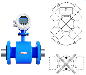
Vertical pipe installation
When measuring fluids containing powders, the flow meter should be installed on a vertical pipe with the fluid flowing upward. This can reduce the influence of bubbles in the liquid.
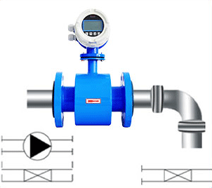
Installed in inlet and outlet pipes
Install between elbows, pumps and valves, and between standard inlet and outlet pipe sections to achieve the highest measurement accuracy.
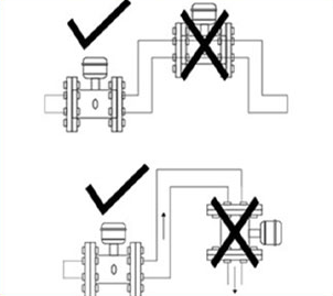
Full pipe installation
The sensor must be completely filled with liquid, and the following two points should be avoided: 1. The flow meter is installed at the highest point of the pipe. 2. It is installed on a vertical pipe with a free outlet.
Flange Electromagnetic Flow Meter Full pipe installation
Electromagnetic flowmeter data download:
Electromagnetic flowmeter data download